Inverter
- General Details
Low Voltage Inverters List
Name Description Model No. Rated Voltage Capacity Sensorless Vector Control Inverter WIN.V63 220-380V 0.2-400kW Closed-loop vector Control Frequency WIN-VC 220-380-860V 1.5-1000kW V/F control frequency inverter for general application WJN.9G/P 220-380V 1.5-1000KW High Performance Vector Control Inverter WIN-9GV 1140-2300V 18-630kW Escalator Inverter WIN-V6E 380V 5.5-37kW Energy-feedback and 4-quadrant Inverter W1N-9E 380V 15-75kW Oil Extractor Energy-Saving System WIN.PSS-ER/EP 380V 18-75KW General Purpose Energy-saving System WIN.PSS-G 380V 1.5-1000KW Injection Machine Energy-saving System WIN-PSS-lV 380V 7.5-75kW Pump & Fan Energy-saving System WIN-PSS-P 380V 18-1000kW Name Description Model No. Rated Voltage Capacity Energy-feedback Braking Unit WIN-9U-PFB 380V 40AJ80A Resistance Energy-consumption Braking Unit W1N.9U-RDB 380V 40A/70A/140A Based on years of accumulated application knowhow enables us capable of producing low- voltage inverters’ current up to be 1800A;
Unique low inductance bus structure ensures nice stability of power unit;
The distinctive ventilation, heat and dust-proof design enhances inverters’ high reliability;
Friendly user keypad facillitates Convenient operation.
WLN-PSS-IV series inverter dedicated for injection molding machine applications owns remarkable potential in energy, saving efficiency;
WIN-PSS-C series inverter for air compressor applications, and WLN-PSS-P series inverter for pump and fan applications also dominate a helfy markest share among all other Chinese inverter manufacturers due to their high performance and high reliability. They have become the first choices for high power air compressors, pump and fans.; While Energy feedback- and four-quadrant inverter system has been extensively used in the oil field extractors, submersible pumps, elevators and small mine hoist, etc. - Techical Info
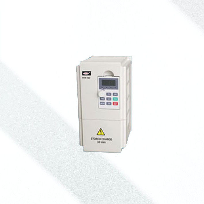
WIN-V63 Sensor less Vector Control Inverter
Voltage rating: 220V/ 380V Power rating: 0.2-400KW– Power range: 025-2,2KW for single-phase 220V-240V; 04-400KW for 3 phases 380V 440V. – Stationary and rotary motor parameter autotuning function for option – Inbuilt PLC operation and process PI control – Inbuilt braking unit for 45KW or below models as standard. 93KW or above is equipped with external DC choke. – Multi-step speed operation (up to 16-step speed). – Wobble operation – Continuous operation function upon momentary power failure – Perfect fault protection and auto current limiting function – Positive/negative logic switch input signal for option – 43 functions for input terminals and 25 functions for output terminals – 10 master frequency reference sources and 11 auxiliary frequency reference sources for you option. – 2 terminals for high frequency signal input (max.SOKHZ), 1 terminal for high frequency signal output (max. 50KHz) – Frequency reference sources and run command sources can be easily switched online, bringing more convenience for debugging arid operation – Inbuilt RS 485 communication port (MODBUS protocol) Scope of Application:
WLN-V63 Series inverter is a general purpose model. It is suitable for inertia load applications, potential load applications and other applications with high requirement on response time; It is also much applicable for pump and fan applications in power plants, iron & steel plants, mines, chemical plants. HVAC, etc. as well as mechanical drive control applications in the fields of textile, manufacturing, paper-making, wire-drawing, printing. etc.
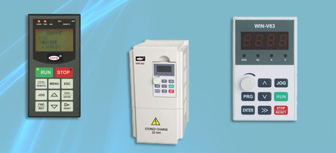
Keypad FunctionKey Name Color Function PRG Program/exit Gray Enter Or exit programming status ENTER Enter/confirm Gray Enter lower level menu or confirm data >> Shift Gray In editing mode, pressing this key to select the bit to be modified, In other mode, this key is used to scroll through the parameters. V Decrement Gray Decrease value or parameter A Increment Gray Increase value Or parameter RUN Run key Green Press this key to run the inverter in the mode of keypad control STOP
RESETStop/reset Red Press this key to stop or reset the inverter JOG Jog key Gray In keypad control mode, press this key to start jog operation. Technical Specification
Items Spesification Rated voltage and frequency 3 phase. 200V — 240V. 50Hz/60Hz; 3 phase. 380V – 440V. 50Hz/6OHz Allowed fluctuation voltage fluctuation: within ±10%: voltage imbalance: <3%: frequency fluctuation: within 5%. Output voltage 3 phase, 0 – 220V; 3 phase , 0-380V output frequency 0 – 400.0Hz Overload capability 150% of rated current -2 Min: 180% of rated current – 10s Control mode Open-loop vector control; V/F control. Run command reference mode By panel ; by terminals; by host machine via series port speed setting mode Digital setting by panel ; analog setting; by series port or other frequency setting mode speed setting precision Digital setting: ±0.01%( – 10C – 40C) ; analog setting: 0.05% C 25C±10C ) Speed setting resolution Digital setting : 0.01Hz analog setting : 1/2000 of max. frequency speed control precision Open-loop vector control:±0.5%; (25C±10C) speed control range Open-loop vector control: 1 : 100 Torque control response Open-loop vector control: < 200ms start torque Open-loop vector control: 180% of rated torque/0.5Hz torque control precision ± 5% Reference voltage supply Output 1 port, +10V, 5mA control voltage supply output 24V. 200mA; Analog input 2 ports. All voltage0 – 10V , A12 curient/voltaage optional 0-10V / 0-20rnA DC analog meter output 2 ports, 0- 10V / 0 – 20mA DC , current/voltage optional Run command input 2 ports. FWD : forward operation; REV rerse operation Programmable connector input Totally 8 programmable digital signal input terminals (X1—X8). X7 and X8 can receive high speed pulse signal.Note: For 3.7KW and below models, there are totally 5 programmable digital signal input terminals (X1—X5). X4 and X5 can receive high speed pulse signal. DO frequency signal output 1 port, high-frequency signal output(programmable) Collector open-loop output Two ports:Y1,Y2. Y2 can be selected as puke output(3.7KW or below, only Y1 available) Programmable relay output 1 port RA/RB/RC, contactor capacity 250V AC/3A or 30V DC/1A Serial communication port cR5-485 connector RS485.,RS485- 4-digit LED display frequency reference, output frequency. output voltage, output current, motor speed, output torque, fault code, etc.. indication lamp Parameter unit, RUN/STOP status, special status, charging status. Requirement on Ambient temperature -10C – 40’C • with fluctuation < 0.5C/Min:Deration above 40C, The output current should be derated by 2% with the increase of per 1C. The allowed highest temperature is 50C humidity Less than 95% RH, No condensation viberation Less than 5.9m/ 52 (0.6g) Storgate temperature -40C – 70C Enclosure IP20 Cooling mode Forced air cooling(natural cooling for the inverter with 3.7KW or below) - Detail
WIN-VC Closed-loop Vector Control Inverter
Voltage rating: 220V, 380V, 660V Power rating: 0.75-1000KW (>355KW is V/F control)Main Features:
– Suitable for the large inertia applications, potential load applications and applications with high requirement in accuracy, response time and torque.. – Four control mode for option: V/F control, V/F control with PG, vector control, vector control with PG. – Massive advanced functionalities available: energy saving control, speed control, slip compensation, torque compensation, moment control, zero servo control, motor parameter autotuning, parameter copy, etc. – High starting torque at low speed: 150% 1Hz (0Hz in the mode of vector control with PG) – Speed control range hits 1:1000; Speed control accuracy hits 0,02% – Output frequency accuracy: + – 0.01% – Multi function input/output terminals, multi -function analog input/output function and serial communication function make operation more convenient. – Perfect parameter online monitoring function, fault analysis function, protection and alarm function guarantee reliability of the invertere. Keypad Function
Key Function LOCAL / REMOTE Control by keyboard/control by control – loop terminal MENU Options for 5 modes. ESC Go back to the previous page RESET To select the displace of values DATA / ENTER To define the mode, parameter and settings. ^ To select the parameter code or increase the setting values. v To select the parameter code or decrease the setting values. JOG Press this key for inching operation whilee the command is given by keyboard. FWD / REV To switch the motor’s rotating direction in the condition of keyboard operation, RUN Press this key to start the inverter in the conditional of keyboard operation, meanwhile, the light of run will turn on STOP Press this key to stop the inverter in the conditional of keyboard operation, meanwhile, the light of stop will turn on.
In the condition of terminal control operation, to enable or disable the function of this key by choosing the parameter o2 er 02.Circuit Diagram
Item Terminal Signal Function Function Description Control signal 1 Forward / stop Inverter runs forward when connected, stops when disconnecled Terminal 3 – 8 are multi-function terminals 2 Reverse / stop Inverter run reversely when connected, stops when disconnected 3 External fault input Input exteinal fault when connected, and not when disconnected 4 Fault reset To reset fault when connected 5 Master / auxilliary speed switch Auxilliary frequency command when connected 6 Multi-step speed command 2 Effective while connected 7 Jog command Effective while connected 8 Coast to stop Effective while connected 11 switching value input common terminal Analog input signal 15 speed command power supply +15V Speed command setting power supply terminal 33 speed command power supply -15V Speed command setting power supply terminal -15V 13 Master frequency command 0 – 10V/100% frequency, -10 – +10V/-100% – +100% frequency
4 – 20mA/100% frequency14 16 Auxilliary frequency command 0 – 10V/100% frequency,- -10V/-100% – +100% frequency 17 Common terminal Common terminal of Terminal 13 & 14 12 Shielded earthing terminal To connect the sheath of the shielding wire Digital Output Signal 9 Operating signal To connect when operating Multi function contact output 10 25 Zero-speed output To connect when the frequency is the lowest Multi function analog value monitoring 26 Speed arrival output Frequency reference within-+2Hz is low level. 27 Common terminal of terminal 25&26 18-20 Fault contact output To fail while terminal 18 and 20 re connected: and terminal 19 20 are disconnected Analog Output Signal 21 Frequency meter output 0-10V/100 frequency Multi function analog value monitoring 1 22 Analog input common terminal 23 Current meter output 0-5V/100% current Multi function analog value monitoring 2 Supplementary power supply +15V +15V Save level as terminal 17 GND +15V common terminal +24V +24V Common ground with terminal 1 – the current is below 100mA - Detail 2
WIN-9(G. P. T. H) – T4 Standard Inverter
Voltage rating: 380V Power rating : 1.5 – 1000KWMain Features:
– This series inverter is applicable in the fields of oil, chemistry, plastics, paper making, foods, cement, printing and dyeing. metallurgy, water supply, HAVC, etc.;= – SPWM technology enables this series inverter with rated torque output at low speed, powerful load capacity;
Inbuilt PlD function, facilitating online parameter adjustment.;– Perfect protection function and fault diagnosis system greatly enhance the inverter’s reliability and stability; 11-200KW models adopt the sealed dust-proof enclosure, prolonging the inverter’s service life; – 11-200KW models adopt the sealed dust-proof enclosure, prolonging the inverter’s service life; – Independent cooling air channel with low wind resistance, ensuring good cooling efficiency; – Main circuit low induction design and optimized components layout enhance the inverter’s load potential; – Inbuilt Keypad as standard, with extension for option (Max. extension: 50m) – Hitachi 32-bit MCU, making the current waveform more close to the sine waveform. Less harmonics and low noise; – Two-line LED Keyboard display: two different operating parameters can be displayed at the same time. – 4 programmable output terminals (2 for programmable relay output, 2 for open-collector output); – Standard operation mode (RUN/STOP), 2-wire operation mode (FOR or REV/STOP), and 3-wire operation mode for option; – Manual voltage output expands scope of application; – Upto 75KW models have inbuilt braking unit for option – Inbuilt RS-485 interface (MODBUS Protocol) WIN-9(G. P. T. H) – T4 Standard Inverter
Voltage rating: 380V Power rating : 1.5 – 1000KWKeypad Function
Key Function PRG To enter the menu of functions SET To exit from the data modification of function items;
To modify the monitored contents in the lower LCDESC To store the values while setting the parameters.
To modify the monitored contents in the upper LCDV To increase the function code or its content To increase the function code of fault display. ^ To decrease the function code or Its content, To decrease the function code of fault display. FOR To start the inverter by issuing a command of forward rotating In the mode of keypad control. STOP / RESET In the event of operation: to stop the machine according to the preset deceleration time.
In the event of fault: to reset (reset Is disabled while fault existsJOG Press this key for reverse rotation in the condition that the machine is under keypad control, and the value of F014 is 1, Circuit Diagram
Category Terminal Code Name Function Description Control Signal COM +24V common terminal – FOR Forward Effective while connected to COM FREE Free stop terminal effective while connected to COM RST Reset terminal effective while connected to COM X1-X6 multi-function input terminal Programmable multi-functional contact input switch output signal TA1, TB1, TC 1 fault contact output 1 to fail while terminal TA and TC are connected; and terminal TB and TC are disconnected. (programmable) TA2, TB2, TC2 fault contact output2 Y1, Y2 output signal In the course of operatlon,open collector Open Collector signal output (programmable) analog output signal FM frequency meter output 0-10V/100% frequency;multi.function analog value monitoring CM Current meter output 0-5V/100% frequency;multi-function analog value monitoring V10 Signal power supply 10V Analog + 10Vpower supply VG Preset analog input voltage 0-10V / 100%0-5V/100% IG Preset analog input current 4-20mA / 100%0-20mA/100% VFA, VFB voltage feedback input signal 0-10V IFA, IFB Current feedback input signal 4-20mA GND common – supplementary power supply + 24V, COM 24V supplementary power supply + 24V WIN-9GV-T11 Powerful High Performance Inverter
Voltage rating: 1140-2300V Power rating: 75-630KWMain Features:
System Features :
The inverting circuit adopts neutral point 3-level PWM structure:– Simple circuit structure enhances the inverters reliability. It can realize higher voltage output without serial connection of power components – Less harmonics, output voltage waveform is close to sine waveform; – Small dv/dt, no special requirement on the motor’s insulate performance; – Compact Performance Features:
– Suitable for the high-end heavy inertia load applications, potential load applications and applications with high requirement on accuracy and response; – For control modes for option: V/F control, V/F with PG, vector control, vector control with PG. Motor parameter autotuning function; – High torque output in vector control mode: speed control range hits 1:100; – Zero-servo function; – Energy-saving function makes the motor working in the best condition. Auto operation can be realized with PlD regulator; – Slip compensation greatly stabilizes the motor; – Inbuilt auto torque compensation function; – Torque control function allows the motor work with constant torque; – Auto reset function – Friendly LCD keypad, – Online parameters modification and copy; – Less pollution to grid - Order Enquiry
Contact form description text
- Comments